Project 2
Project 2 uses a combination of the model created in Project 1 and Dynamo in a way that helps improve the model. Below is a video summarizing the Dynamo code incorporated into the model.
Video Project 2 - Dynamo
The wall in the center of the Al Hamra Tower has windows that change angle from the center to the ends of the wall. This can more clearly be seen In Figure 1.
Figure 1. Windows in Actual Building
In the Revit model created in Project 1 the panels in the front wall were not placed as in the design of the actual building. Therefore, to incorporate the design of the building into the model a Dynamo code was done that arranged 14 different panel types that represent the different windows present in the building. To start this, one of the panels was placed to the entire facade as shown in Figure 2. Then the Dynamo code is run and the final result can be shown in Figure 3.
Figure 2. Wall with no window
Figure 3. Wall with the windows of the original design
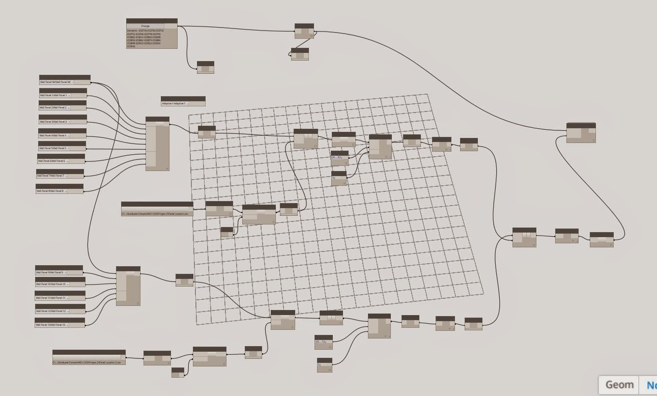
Figure 4 shows the entire Dynamo code that is used.
Figure 4. Complete Dynamo Code
In Figure 5 a section of the code in shown. Here, the different window families are arranged into a list and then using a Python script and an Excel file the panels arranged into the pattern desired. In Figures 6&7 the Python script and Excel file are shown. As mentioned before, there are 14 panels used and the portion of the script only shows 9 panels being used. This is because the Python scrip can only be used up-to an index of 9 because after 9 it separates the values into single integers. Thus a 10 will be slit into a panel 1 and panel 0. Therefore, two list where created and then combined.
Figure 5. Dynamo Code Selection and Rearranging Panels
Figure 6. Excel File with window pattern
Figure 7. Python Script
The portion of the Dynamo code in Figure 8 shows the selection of the initial panels present in the building, and then transposing them in order to match the pattern done when creating the list of the new windows. Then in Figure 9 the index values are retrieved form the new pattern and then the old index values are replaced with the new ones. In Figure 10 we can see the new panels placed in the entire wall.
Figure 8. Dynamo Code New Panels
Figure 9. Combining the two lists
Figure 10. Final facade with the new panels
Finally, Figure 11 and 12 show renderings of the new model. It can be seen that the pattern closely matches the pattern in the original building.
Figure 11. Closeup rendering of the windows
Figure 12. Building Rendering.
The Al Hamra Tower is a 1350 ft(412 meters) skyscraper located in Kuwait. The building was built between 2005 and 2011, and houses offices, a mall, a health club and a food court. The fold in the building Maximizes views, while at the same time minimizing solar heat gain.
The design of the fold was done by taking a square with rounded edges, cutting a right triangle out of it, and rotating the angle 90 degrees form the base to the top. This is illustrated in the figure bellow.
For the parametric design of the building I used two separate mass models to create the model, one for the top peak of the building and the other for the section with the fold. For the section with the fold I created a parametric generic model in Revit that contained 3 points. One point located the center of the building, while the other two rotate and moves up as the n parameter is increased.
This file was then imported into a conceptual mass where the square form was created. With the points, I created the triangle shape at several levels of the model and created a void. The angle at which the fold twist can be changed, from 90 degrees to any angle desired.
Similarly, the top portion of the building was created using a generic model and a conceptual mass model. The only difference is that the only two parametric points where used.
The main problem with this model is that when cutting a curved shape with a void, the parametric panels I created go out the lines.
The fallowing are some renderings and pictures of the final result.


No comments:
Post a Comment